|
|
|
|
Partea I:
Propulsii similare OZN (Performantele Masinilor Timpului)
Partea a II-a:
Dezlegarea unor mari enigme |
|
C O N T E N T S |
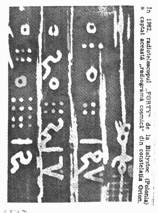
I give the following interpretation to this radiogram : the intelligence is represented by an artificial network- the radiogram expressing schematically network as a result of an intellectual activity respectively an intelligent thought, from that mind - , and being located in the whole functioning system, respectively on a non-turning central discoidal landscape means (asymmetry) having on the top and on the bottom, on the same vertical axis of symmetry a turning platform on contrary directions (repr. graphic of exponential increase of acceleration, mass symmetry, successive asymmetry of the vertical turning axis suggesting controlled disequilibria of turning masses and the inertial effect of the disequilibria, two gaps suggesting the replacement of the biped walk by an artificial propulsion system, gaps which result by a logical succession on that artificial propulsion that like two equal and opposed heating chambers, the schematic representation of the zigzag working, each speed of displacement growth is graphically represented by a column of dots, speed which can easily be doubled etc.). At the same time the modifications of the relative centre placed on the same vertical symmetric axis from the turning movement are given successively, where the following platform schematically represented that it has always a mass: a bigger diameter for the flight stability (gyroscopic effect) being successively and schematically presented even in the mode of the inertial zigzag displacement to obtain (as we will show further in the description of this invention) the successive increasing acceleration of the hole functional system - independently of the flow speed of gases through a reactive sustain (effusor), - as a result of the burning gases at a constant pressure. Due to the successive kinetic energy saved and released (Ec) of the turning moving corpses and respectively above the light speed of around 300.000 km/sec., related to our stage of development, does Cosmically Radiograms enable me to certify firmly that we are not alone in Universe and that it exist some civilisations much more technologically developed and without any aggressive intentions, because they send us messages. The technical problems that are solved by this invention are characterized by the fact that all the disadvantages of the prior solutions are removed ( and especially the classical way of overcoming the gravity and entering in Cosmos by rockets having their own steps ) and can be produced at a wide range, flying saucers, as new ultra rapid means of transporting persons and goods, with extremely high speeds, accelerations and brake ( using the propulsion system rotated by 180 grades ), with sustentation at a certain point in space, with fast and keeped under control changes of the route in any direction, with concomitantly inertial movement in zig-zag,- enabling the overpass of the light speed but complying with the laws from Physics known till now, with turning from the propulsion based on constant pressure to the movement in the atmosphere, at working like a rocket engine when flying in Cosmos, or working like a static reactor when flying at very high altitude in the Earth atmosphere, having a new way of annulment of gravity�s influence over each rotating sector as integrant part of the discoidal platforms due to the centrifugal forces and secondary like another ant gravitational effect due to appearance of a depression uniform uniformly distributed on the exterior surface of the upper carcase as a consequence of the feeding air absorption by the radial single centrifugal central compressor with double effect and frontal pallets in steps, interspersed and with a movement in contrary senses. - The principal new element of the invention is the fact that the superior discoidal turning platform (12) solidarilly with flange (17) and the superior frame(25) as the inferior discoidal turning platform (13) solidarilly with flange (28) and the inferior extern frame(32), are not a compact indestructible mass but are made up by assemblage - but with a radial level of liberty - by equal couples of circular crown sectors diametrically opposed located (preferentially grouped by four or six according to the size of the vessel by much more couples for each turning platform) each couple in a turning movement (on contrary directions) generate centrifugal forces tending to remove them (by expandation) from instant relative turning centre. Each couple of sectors being located symmetrically and diametrically opposed generates centrifugal forces with the same size and diametrical opposed by their direction having the original centre placed on vertical symmetrical axis (z-z) of the whole functional system and being functionally connected through a hydraulically connection of energy and force. Between the exterior frames and the turning platforms which compose each of them one circularly crown sector, being constructively located: goods, food stock, fuel and liquid symmetrically placed at equal quantity in each discoidal sector through volume segment of circular crown which form together the two turning circularly platforms (12) respectively (13). Those centrifugal forces are put together from all sectors with a radially grade of liberty which constitute the two turning platforms due to the hydraulic amplifier of force and energy (21) with the same shape and construction with the genuine part presented in the Bibliography [2, page 279], linked by circuits of hydraulic pipes which links all those circular crown sectors generating by putting together for each turning platform an unique resultant force placed right on the symmetry axis of the whole functional system (z-z), vertically orientated and on a contrary direction to gravitation as shown in Fig.(2). The addition, the amplification, the auto-centralisation and the progressive and concomitant annulment of stokes are realised with the progressive increase of revolution. In contrary direction of the two turning platforms, the technical processing is realised especially due to the effect of the banded plane (breakdown) existing in the amplifier of energy and force (21) mentioned and similar with the one described and presented in the Bibliography (2) pag. 152 - 156, picture from pag. 279 and represented as the place on the cinematic scheme of the whole system from Fig. Nr. (3), respectively the machine parts (21). Thus, the bigger is the mass of those circular crowns put together and combined in a turning platforms and the bigger is the area of the angular turning speeds (w) respectively the revolution (n), the bigger will be also the centrifugal resultant forces, respectively the bigger will be the total kinetic energy accumulated (Ec.tot) due to rotation being added and accumulated and conserved by the superior platforms (12) and the inferior one (13) . The kinetic energy stocked will be directly proportional with the same parameter proportional with motor (Cm) rotator generated by the flow of gases from the two burning chambers opened - in the isobar evolution - at a constant pressure (4) and (5) [statoreactors] diametrically opposed and fixed at the extremity of the fix stationary platform (1) able to work under the three different functional ways which were above described. The centrifugal forces diametrically opposed [linked between them by the hydraulically circuits with force an energy] generated by the volumic sectors of diametrically opposed circular crown are those dozed and permanently controlled through an hydraulic command system integrated and the pressure generated by the hydraulically auxiliary pump controlled from the cockpit by a remote control, two assisted engines - one of them on each turning platform - amplifies and reduces up to annulment and weight of the central discoidal system respectively of the platform (1) through a transfer in action of the weight of this one from the vertical direction - as kinetic energy on horizontal plane of rotation of the two turning platforms, according to the cinematic scheme of Fig. Nr.(1) and the graphic representation of Fig. Nr. (2). Another new element of the invention is that due to the big diameter of the unique radial centrifugal compressor in steps, through the alimentation of this by the air that gets in the first step by of compression through the holes (26) uniformly distributed on the superior frame(25), is obtained also a specifically uniform depression distributed on the surface of the superior frame 25, is alsio obtained a specifically uniform depression distributed on the surface of the superior frame, and that depression has as immediate effect a tendency of absorption up of the whole functional system, and consequently the obtaining of a secondary ant gravitational effect. So, supposing that the exterior diameter of the superior frame (25) is 12 meters respectively 1200 cm and the internal diameter 2 metres respectively 200 cm, and the specifically depression is (-0.01) ) [kg.f/cm2], it will result a active superior surface frame (25) of around 1,099,000 cm2 , multiplied by 0.01 it results an ascension force which reduces the total weight at the taking off with around 10,990 kg, which is not small because at the taking off, all the genuine parts are solicitated at maximum. Another new element of that invention is that, under the regime of flight in the atmosphere, at a high speed it appears both necessary and constructively favourably the opportunity of alimentation of the reactive burning chambers (4) and respectively (5) - in parallel - by the forced admission of air which is naturally compressed in front of exterior frames (35) respectively (32). So, the natural and caught compressed air on surfaces of admission relatively very big (similar to a convergent piece approximately rectangular or square but divergent due to the curved cylindrical surfaces) get in towards the statoreactors through the holes (27) uniformly distributed on the circumference superseding the compressor by the controlled of the opening or the closing of the inelar diaphragm (36). That technical combined solution of feeding permanently the necessary and sufficient quantity of air for combustion, as far as it is known, at very high altitudes the air density necessary for the combustion considerably decrease, anyway, due to the possibility of the admission and the obtention of the air from big surfaces, and constructively profiled, some big debits respectively big quantities of air can be provided due to the natural compression. Comparatively, the classic turboreactors and statoreactors currently used in the aircraft industry do not benefit of that big constructive advantage because of the relatively reduced surface of the admission filters which are severely restricted constructively because of their reduced diameter. Also as a big advantage and at the same time favoured and also as an innovating aspect of that invention is the fact that turning of the superior (12), and inferior (13) frame in the contrary direction, and the displacement at the superior speeds (greater than de 1000 m/sec), the natural air compression located in front of the direction of the promotion can be optimised and increased by a radial shaping of the extremity in that zone of the admission orifices (27) - in relief - and adequate to those two rotating carcasses, the naturally compressed air from the front of the displacement direction being in this way obtained, directed and captioned towards the centre from the horizontal plan of the entire system where the natural compression of the air has the maximal value. The big tangential speeds (Vt) necessary of the ranged in steps blades of the unique centrifugal compressor in steps that are constructively interpenetrated, are very easy to perform practically and at very low revolutions of the rotating disks (6) and inferior (7) solitary each of them with the rotating platform (12) respectively (13), according to the relation (Vt) = 3.14.D.n/60) [meters/sec] where (Vt) is the tangential speed of the rotating platform, (n) is a rotating platform revolution in [rot/min], and (D) is the average diameter of the blades location, so by example if the revolution (n)=200[rot/min] and (D)=15[meter] it results; (Vt)=3,14.15.200/60 = 157 [meter/sec] but as the two turning disks blades (6) respectively (7) have contrary rotating directions, it results Vt = 314 (meters / sec) entering already in the supersonic regime. That supersonic speed obtained at a only 200 [revolutions/min] is enough to perform comparatively, relations of compression favourable, practically - according to the desire, being able to perform very easily the aimed purpose due to the tangential speed. They can be lightly increased and - with no constructive restriction - by enlarging the circumference or by the light increase of the rotating platform revolution.
Another innovation of this invention is characterised by the fact that by this proceeding of construction of the whole functional system, after the taking off, the flying saucer can still be propelled and by The rotation centre of the turning superior platform (12) is commuted- at the extremity of the latter, this thing being possible practically by the temporary coupling and of the very short duration of the superior platform (12) with the stationary platform (1) at the same point from the extremity located at the distance (d) by the sabots (S1) respectively (S2) for the inferior platform (13), having as the immediate result the obtention of one force that pull all the system forward. That force is made evident by the Theorem of Steiner from the physics, that theorem being applied to the movement of a body that is moving rotatively like this: knowing the value of the inertia moment that passes through the centre or of the mass noted with (I) we will have: (I) = 1/2.M(R2+r2), Where: (M) is the mass of a body as a cylindrical ring, the moment of inertia can be calculated (I1) = (I) + (M.d2) respectively calculating similarly the kinetic energy (Ec) = 1/2 (I+M.d2).w2 where (w) is the angular speed, it results that at another instantaneous centre of rotation located on the parallel axis of rotation (z1-z1) , the moment of inertia (I1) is much bigger comparatively with the moment of inertia (I) conserved at the kinetic moment respectively in the kinetic energy (Ec) accumulated and conserved by the training in the rotation of the two turning platforms, the kinetic available energy having a very big value and being able to liberate hardly instantaneously and is in a mechanical work (LM) = (Ftsupl.d). But as D(Ec) = (LM) the supplementary force of traction value can be established (Ftsupl) resultant as effect of the coupling of the sabots (S1) and analogous for the inferior platform by the coupling of the sabots (S2). |